SYNCHRONIZED ENGINEERING ARCHITECTURE

From Hardware to Control Software. One Unified System.

We engineer custom electronic boards, embedded firmware, industrial communication, and PC/tablet control interfaces under a single engineering architecture.

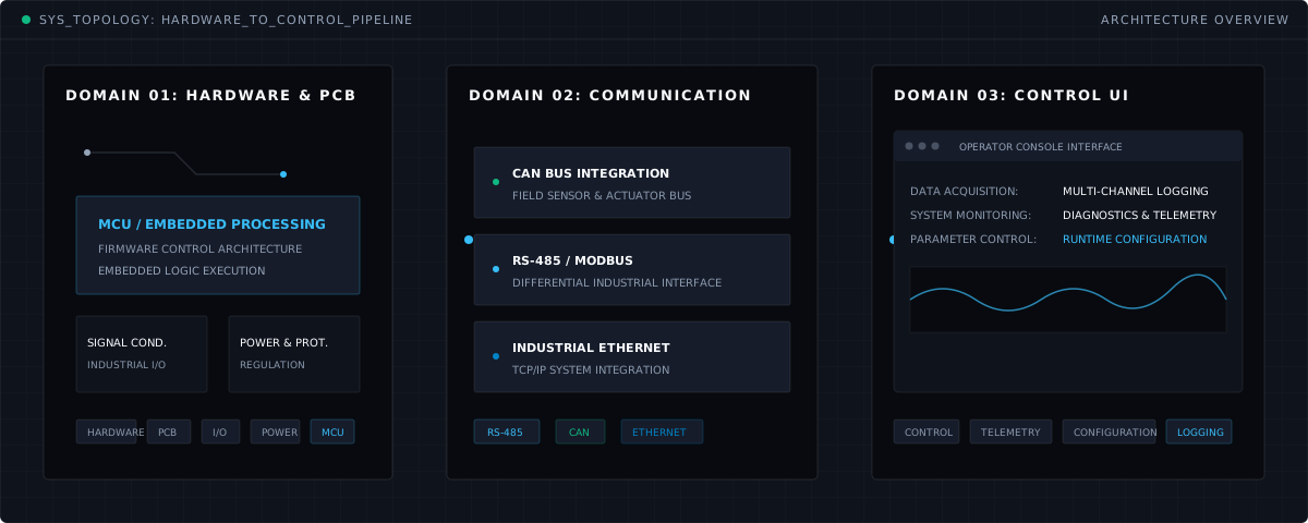
TOPOLOGY: UNIFIED_SYSTEM_ARCHITECTURESYSTEM ARCHITECTURE
SYNCHRONIZED REALITY
Integrated hardware, industrial bus, and control software architecture overview
[01] DOMAIN: HARDWAREPCB

Custom Electronic Hardware

Power regulation, protection circuits, signal conditioning, and industrial I/O.

HARDWAREPCBI/OPOWERMCU
[02] STAGE: PROCESSEMBEDDED

Embedded Processing

MCU firmware, sensor processing, and hardware control logic.

[03] DOMAIN: COMMUNICATIONFIELD BUS

Industrial Fieldbus

RS-485, CAN, and Ethernet physical bus architectures.

RS-485CANETHERNET
[04] DOMAIN: SOFTWAREPC / TABLET

Operator & Control Interfaces

Telemetry and system data visualization, runtime configuration, and device management.

CONTROLTELEMETRYCONFIGURATION
[05] STAGE: ACTUATIONPHYSICAL

Physical Actuation Drive

Control and actuation of valves, motors, relays, and field outputs.

System Loop Pipeline

  1. 01
    SENSEPhysical Sensor Data Acquisition
  2. 02
    PROCESSMCU / Firmware Processing
  3. 03
    COMMUNICATEIndustrial Bus Transmission
  4. 04
    CONTROLOperator & Telemetry Control
  5. 05
    ACTPhysical Actuator Output
WORKING SYSTEM LOOP

Not Just a Board. A Working System.

Electronic hardware, firmware, industrial fieldbus, and operator software are engineered together in a single synchronized architecture.

  1. [01]
    STAGE_01

    SENSE

    Physical sensors and field inputs

  2. [02]
    STAGE_02

    PROCESS

    MCU / firmware processing

  3. [03]
    STAGE_03

    COMMUNICATE

    Industrial fieldbus communication

  4. [04]
    STAGE_04

    CONTROL

    PC & tablet control software

  5. [05]
    STAGE_05

    ACT

    Physical actuation & system output

ENGINEERING DISCIPLINES

Three Synchronized Engineering Layers

We do not build hardware, firmware, and control interfaces as isolated silos. We engineer them as a single synchronized engineering stack.

[DISCIPLINE 01]HARDWARE & PCB

Custom Electronics

From schematic capture to multi-layer PCB layout, engineered to withstand demanding industrial field conditions.

ENGINEERING SCOPE

  • Schematic & multi-layer PCB design
  • Analog & digital industrial I/O stages
  • Power regulation & protection circuitry
  • Sensor interfaces & signal conditioning
  • Industrial connectivity & terminal architecture
  • EMI/EMC design principles
[DISCIPLINE 02]FIRMWARE & MCU

Embedded Systems & Firmware

MCU-based embedded firmware for hardware control and system logic running on microcontroller cores.

ENGINEERING SCOPE

  • MCU-based firmware architecture
  • Low-level board support packages (BSP)
  • Sensor acquisition & digital filtering
  • Watchdog & hardware fault recovery
  • Industrial communication protocols
[DISCIPLINE 03]SOFTWARE & UI

PC & Tablet Control Software

Desktop and tablet operator consoles for field technicians and control engineers.

ENGINEERING SCOPE

  • Operator interfaces & control panels
  • Multi-channel telemetry visualization
  • Runtime system parameter configuration
  • Calibration & diagnostics utilities
  • Event & operational logging systems
  • Direct hardware actuation control
CAPABILITY MATRIX

Technology & Communication Matrix

Industrial communication and control technologies used across our engineering workflows.

COMMUNICATION CAPABILITIES
TechnologySpecification
RS-485 / ModbusIndustrial Differential Bus
CANIndustrial Field Network
Industrial EthernetTCP/IP Network Communication
Wi-Fi / BLEWireless Field Diagnostics
EMBEDDED SYSTEMS
TechnologySpecification
ARM Cortex-MMicrocontroller Architecture
ESP32Connected Field Nodes & Gateways
Embedded C / C++Embedded Firmware Development
CONTROL SOFTWARE
TechnologySpecification
PC Control InterfacesIndustrial Operator Stations
Tablet InterfacesField Diagnostics & Inspection
Telemetry & LoggingMulti-Channel Data Acquisition
Calibration ToolsField Calibration & Parameters
ENGINEERING METHODOLOGY

From Concept to Working System.

A structured four-stage engineering methodology uniting hardware, firmware, and control interfaces end-to-end.

  1. PHASE_01ARCHITECTURE

    Requirements & System Architecture

    Specification of field constraints, I/O requirements, and fieldbus communication topologies.

  2. PHASE_02HARDWARE

    Schematic & Multi-Layer PCB

    Circuit design, multi-layer PCB layout routing, and physical prototype assembly.

  3. PHASE_03FIRMWARE & CONTROL

    Firmware & Control Software

    Microcontroller firmware loops, industrial protocol handlers, and PC/tablet operator interfaces.

  4. PHASE_04VALIDATION

    Laboratory Validation & Field Testing

    Signal integrity verification, load tests, and closed-loop functional validation.

INITIATE PROJECT // TECHNICAL CONSULTATIONCONTACT CHANNEL PENDING
CONTACT

Let’s Engineer a System Together.

Discuss your project requiring custom hardware, embedded firmware, or control software in full technical detail.

Additional Technical Context & Volume (Optional)
Engineering Files (Optional)0 / 5 FILES (0.0 MB / 25 MB)

    Checking this box initiates our bilateral NDA onboarding process; it does not constitute an automatically executed agreement.

    Official privacy policy and data governance notice is pending approval; link will be published upon corporate release.

    Secure Engineering Pipeline: All uploaded files undergo isolated quarantine inspection and storage.

    Your files are isolated in private quarantine storage; they are never made public or stored in static web roots.

    CONTACT CHANNEL:Pending final configuration